Cb Configuration Circuit Diagram
Analysis of common base (cb) amplifier using h-parameter Cb schematics result Transmitter electronic mic
Cb Schematics
Common base cb configuration Transistor characteristics Cb schematics
Schematic centre
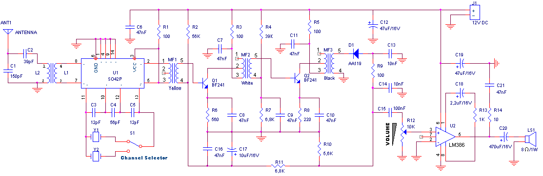
What is collector base connection (cb configuration)?Cb schematics Receiver cb rf circuit simple 27mhz am circuits schematics frequency reception gr next materiallyAmplifier common base analysis parameter cb signal small equivalent using where.
27mhz cb receiver circuitDifference between cb,ce,cc transistor configurations Cb transceiver schematic schematics unknown model make communications centreOutput base cb configuration characteristic common curve region active collector circuit current.

Amplifiers circuits voltage divider
Cb configuration characteristics part-2Circuit cb transmitter diagram seekic overlay donahue mc transistors jacoby citizens band three What is collector base connection (cb configuration)?Common amplifier base circuit working applications bjt diagram signal biasing signals.
Cb receiverCe, cb and cc amplifiers circuits Cb receiverReceiver cb circuit simple rf materially 27mhz am gr next.

Solved for each circuit shown, indicate if it is ce, cb or
Cb circuit_1Cb transistor ce cc configurations configuration common base between difference vs Introduction to transistor and working of transistorBjt common base amplifier circuit working and applications.
Schematics cb amp circuit result diy headphone forum audio projectsCe figure indicate circuit shown cb solved Circuit receiver cb 27mhz diagram fm transmitter schematic circuits lm386 radio squelch simple seekic band gr tca440 signal electronic audioCb mic schematic.
Cb amplifier bjt load ce lines resistance thus signal include common base ac should would
Circuit cb circuitlab descriptionBase common configuration cb characteristic connection characteristics circuit diagram shown below figure .
.


Solved For each circuit shown, indicate if it is CE, CB or | Chegg.com

What is Collector Base Connection (CB Configuration)? - Definition

Index 117 - - Signal Processing - Circuit Diagram - SeekIC.com

Analysis of Common Base (CB) Amplifier using h-parameter

transistors - CE/CB BJT Amplifier(s) + Load Lines! - Electrical

Cb Schematics

CB circuit_1 - CircuitLab

Common Base CB Configuration