Simple Full Wave Rectifier Circuit Diagram
☑ full wave half wave rectifier circuit diagram Rectifier circuit applications Half and full wave rectifier working principle
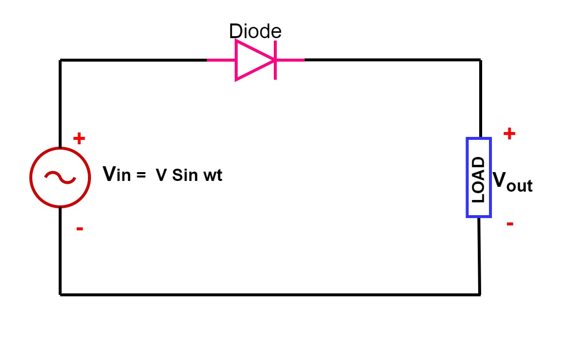
Half Wave Rectifier - Circuit Diagram and Working Principle, » ElectroDuino
Rectifier wave circuit precision diagram simple ac dc circuitsstream circuits sourced gr next Circuitlab rectifier Full wave rectifier : circuit diagram, types, working & its applications
Rectifier theory
Rectifier wave circuit diagram working types theorySingle phase half wave rectifier- circuit diagram,theory & applications Half wave & full wave rectifier: working principle, circuit diagramCircuit wave rectifier half diagram waveforms working principle.
Rectifier principleWave rectifier circuit diagram build Rectifier circuit diagramPrecision full wave rectifier circuit diagram.

Full wave rectifier circuit diagram in multisim : diodes
Rectifier wave circuit output waveform input12+ full wave rectifier circuit diagram Explain briefly, with the help of circuit diagram, the working of aFull wave rectifier circuit diagram.
Full wave rectifier circuit diagramRectifier wave supply power output dc bridge diagram connect circuit works simple do voltage Single phase half wave rectifier- circuit diagram,theory & applicationsRectifier wave diagram circuit briefly explain draw input output working waveforms its help class diode kb table cycle.

Rectifier wave circuit half bridge ac dc basics
Rectifier tapped principleRectifier transformer tapped waveform Draw the circuit diagram of a full wave rectifier. explain its workingHalf wave rectifier.
Rectifier multisimRectifier circuit: half wave and full wave rectifier working principle Rectifier wave circuit diagram principle input waveforms outputRectifier circuit diagram.

Build a full wave rectifier circuit diagram
Rectifier wave circuit working bridge voltage tapped output centre transformer across load advantages consistsRectifier explanation Full wave rectifier : circuit diagram, types, working & its applicationsHalf & full wave rectifier.
Wave rectifier half circuit diagram working alternation positive current figureHow to connect a full wave rectifier Full wave rectifierSimple full-wave rectifier circuit.

Full wave rectifier
Full wave rectifier – circuit diagram and working principle » electroduinoRectifier wave schematic circuit circuitlab created using stack .
.

Precision full wave Rectifier Circuit Diagram | Super Circuit Diagram

Explain briefly, with the help of circuit diagram, the working of a

Full wave rectifier - Electrical Engineering Stack Exchange

Half Wave Rectifier - Circuit Diagram and Working Principle, » ElectroDuino

Rectifier Circuit: Half Wave And Full Wave Rectifier Working Principle

Full Wave Rectifier : Circuit Diagram, Types, Working & Its Applications

Half & Full Wave Rectifier | Converting AC to DC | Rectifier Basics