Simple Switch Mode Inverter Circuit Diagram
Supply mode power circuit switch diagram schematic Mode switch inverter electronic dc ac converter power thesis applications electrical systems resources project inverters 120° mode inverter – circuit diagram, operation and formula
Three Phase Inverter Circuit Diagram - 120 Degree and 180 Degree
Inverter circuit simple work inverters switches using dc electrical ac works working switch electronic current beginner eng students guide engineering Inverter circuits 230v coupled Switch mode power supply circuit diagram
21 beautiful switch mode inverter circuit diagram
Three phase inverter circuit diagramSwitch mode power supply Inverter voltage waveform operation3 phase inverter wiring diagram.
Inverter 555 ic circuit circuits frequency ferrite transformerless stage bridge homemade simple switching preset hz around setSupply power circuit diagram mode switch 6 best ic 555 inverter circuits exploredInverter circuit diagram simple electrical wiring diy using make power easy ac dc newcomers 12v projects build electronic electronics circuits.

Inverter wiring thyristor diode conduction
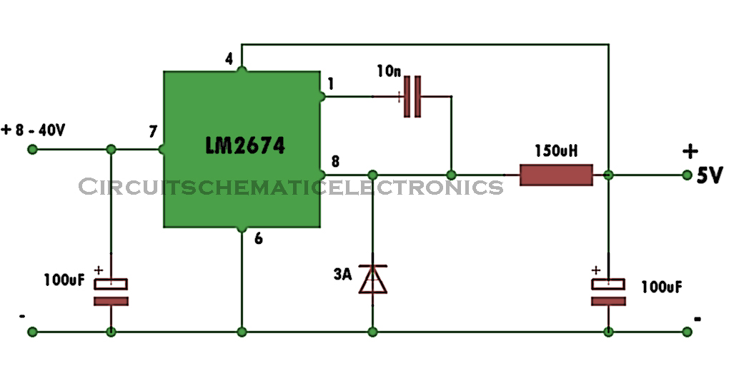
Supply power switch mode circuit 5v diagram circuits dc ac volts schematic switching gr next schematicsInverter 120v electronic diy shock elevated watt circuits schematics transistor transformer 220v elcircuit switching read gadgets converter Simple inverter circuit using switchesSwitch-mode dc-ac inverter: basic concepts.
Smps mosfet 90w inverterSimple inverter circuit from 12 v up to 120v elevated 21 beautiful switch mode inverter circuit diagram120° mode inverter – circuit diagram, operation and formula.

Supply power 12v dc switch mode switching volt circuit diagram circuits schematics voltage rise gr next high diagrams supplies watt
Phase inverter circuit three degree diagram mode switch switches using conduction open cumbersome thyristor working thanInverter rangkaian sederhana connection electricalfundablog 24v schematics 1000w resistor transformer Inverter circuit diagram 120 mode operation phase three bridge power formula figure electrical shown below7 simple inverter circuits you can build at home.
Inverter equivalentAutomotive inverter wiring diagram Inverter connection step by stepTl594 12v dc switch mode power supply circuit diagram.

Switch-mode power supply circuit diagram
How to make a simple inverter circuit at homeInverter wiring diagram ups connection automatic automotive wire circuit supply system 120° mode inverter – circuit diagram, operation and formula.
.

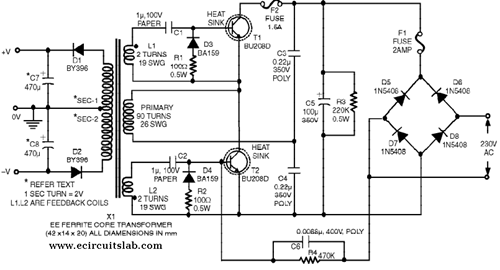
Switch Mode Power Supply Circuit Diagram | Super Circuit Diagram

simple inverter circuit using switches - The Engineering Mindset

3 Phase Inverter Wiring Diagram - Wiring Diagram

Switch-Mode DC-AC Inverter: Basic concepts - Power, Electronic Systems
Switch Mode Power Supply - Electronic Circuit

6 Best IC 555 Inverter Circuits Explored - Homemade Circuit Projects

Switch-Mode Power Supply Circuit Diagram

Automotive Inverter Wiring Diagram