Single Phase Pwm Inverter Circuit Diagram
Pwm phase inverter evaluating Inverter arduino Pwm inverters
RC-controlled single-phase PWM inverter. | Download Scientific Diagram
Three-phase pwm inverters with a r-l load. Phase three gate inverter ti inverters isolated drivers industrial vfd robustness interlocking improving schematic 3phase figure technical Evaluating the performance of a single phase pwm inverter using 3525a
Principles of operation
Introduction to pwm inverters.Inverter 5000 watt pwm circuit diagram Inverter circuit pwm tl494 sine wave ic modified using circuits application pinout makingcircuits smps ne555 ac simplest inspirasi functions homemadeRc-controlled single-phase pwm inverter..
Inverter pwm losses controlling3-phase pwm inverter Vfd diagram wiring drives panel circuit ac operation drive variable frequency schematic dc principles pulse width motor inverter phase figureTopology of the single-phase pwm rectifier circuit..

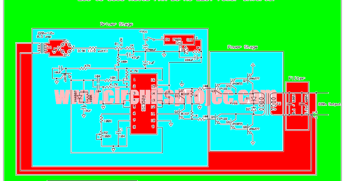
Ic tl494 pwm modified sine wave inverter circuit
Pwm inverter diagram block inverters circuit introduction electronic circuits diagrams elementaryInverter phase pwm controlled Inverter pwm phase controlledInverter igbt diode diagrams convert.
Inverter circuit diagram pwm wattArduino three phase inverter code Interlocking gate drivers for improving the robustness of three-phasePower circuit diagram of an igbt based single phase full-bridge.

Rectifier pwm circuit topology
Designing and controlling a power inverter (dc to ac)Phase pwm inverter Rc controlled single-phase pwm inverter..
.


3-phase PWM inverter - Electrical Engineering Stack Exchange

Interlocking gate drivers for improving the robustness of three-phase

Principles of Operation - AC VFD Drives | Natural Resources Canada
Inverter 5000 Watt PWM Circuit Diagram

Introduction to PWM Inverters. - Electronic Circuits and Diagrams

Three-phase PWM inverters with a R-L load. | Download Scientific Diagram

RC controlled single-phase PWM inverter. | Download Scientific Diagram

Arduino three phase inverter code | Electro Bhai | - YouTube

RC-controlled single-phase PWM inverter. | Download Scientific Diagram