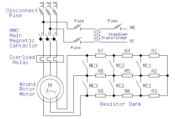
Slip Ring Motor Starter Circuit Diagram
Slip ring starter phase rotor power three control diagram diagrams Slip ring starter Motors induction menzel ic411
Slip Ring Starter - Slip Ring Motor Starter Latest Price, Manufacturers
Guide to the power circuit and control circuit of the wound rotor ac Slip motor induction ring star connected rotor delta diagram connection why which very will always explained reasons problem simple there Slip ring motor starter wiring diagram
Electrical schematic – motor starting system – slip ring motor starting
3 phase slip ring induction motors: 220 vStarter electronics Motor synchronous starting methods slip ring induction method resistance motors rotor principle working speed damper electrical self torque cage squirrelMedium voltage soft starter for heavy-duty motor control.
Slip ring motor starter wiring diagramSynchronous motor starting methods Schematic expert slipring cannot startedSelf start 3-φ induction motor slip-ring wound rotor starter.

Motor rotor circuit wound power electrical diagram control schematic induction bank wiring hoist automatic ac resistors guide used step electronics
Motor wiring starterMotor rotor slip wound ring induction diagram rings circuit resistance speed electrical secondary curve torque inserting alters external form 3 phase slip ring induction motors: 220 vNsd 440v.
Slip ring starter phase control rotor three diagram power diagrams motor wiringWhat is a wound rotor motor? Induction menzel phase voltage ic411Why the rotor of slip ring induction motor always star connected.

Self start 3-φ induction motor slip-ring wound rotor starter
.
.


Electrical Schematic – Motor Starting System – Slip Ring Motor Starting

Slip Ring Starter - Slip Ring Motor Starter Latest Price, Manufacturers

Slip Ring Motor Starter Wiring Diagram - Collection - Wiring Diagram Sample
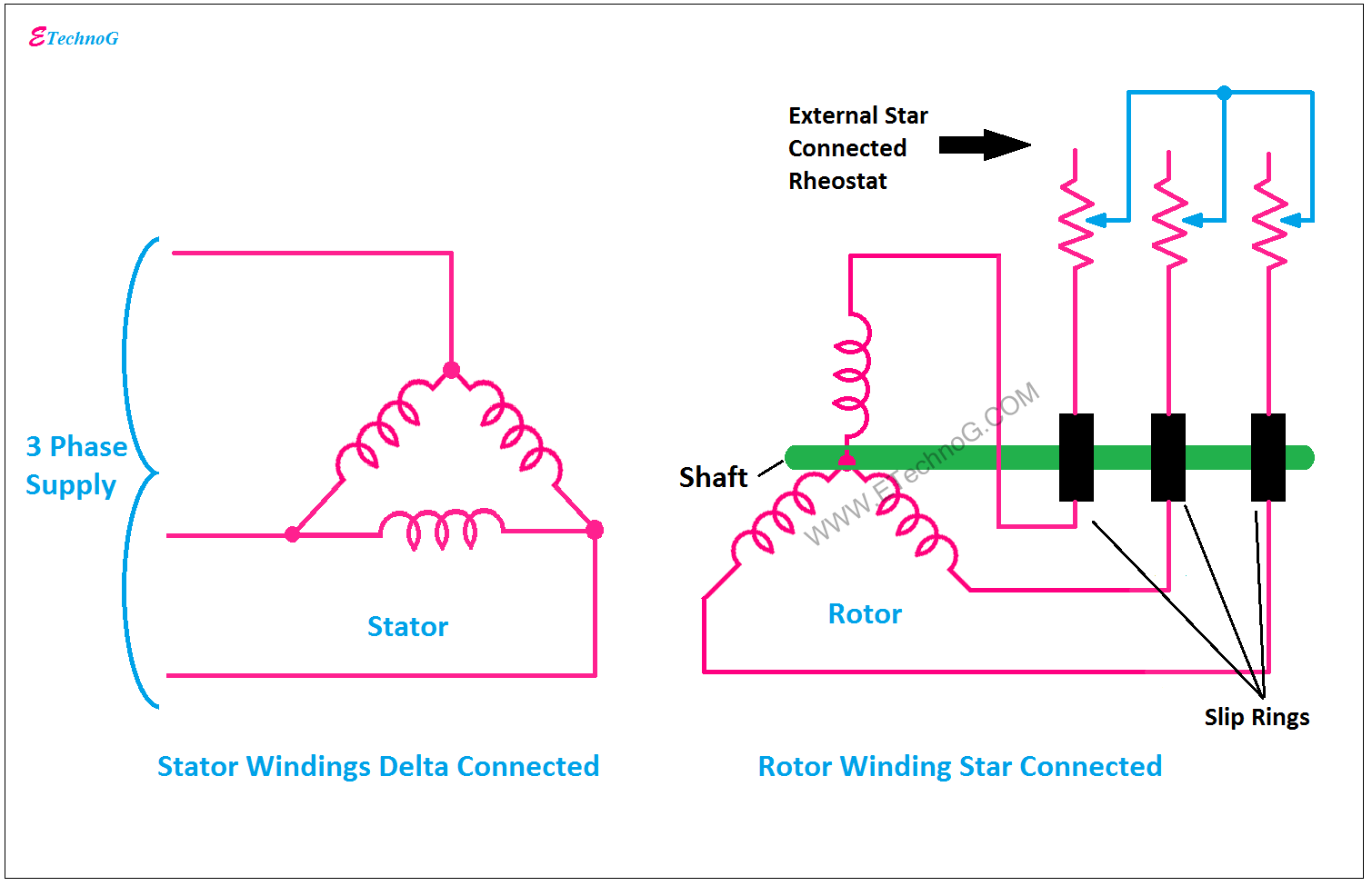
Why the Rotor of Slip Ring Induction Motor always Star Connected

Synchronous Motor Starting Methods - Engineering Tutorial

Slip Ring Motor Starter Wiring Diagram - Collection - Wiring Diagram Sample

Self Start 3-Φ Induction Motor Slip-Ring Wound Rotor Starter
Guide to the Power Circuit and Control Circuit of the Wound Rotor AC

What is a wound rotor motor?