Switch Mode Inverter Circuit Diagram
Three phase inverter circuit diagram Ac switch mode dc inverters chapter ppt powerpoint presentation sinusoidal motor power Inverter circuit simple 120v diagram transistor power 120 ac volt transformer supply electronic control diy elcircuit electronics electrical system watt
12V 2A Switch Mode Power Supply with LP2704A
Ups & inverter wiring diagram for one room / office Switch touch simple two inverter gates using toggle 2008 august 120° mode inverter – circuit diagram, operation and formula
6 best ic 555 inverter circuits explored
Phase circuit inverter circuits three generator homemade simple push pull diagram power bridge driver make single into projects arduino railInverter 555 ic circuit circuits frequency ferrite transformerless stage bridge homemade simple switching preset hz around set Adjustable 0-100v 50 amp smps circuit ~ electronic circuit projectsInverter circuit diagram 120 mode operation phase three bridge power formula figure electrical shown below.
Smps circuit components supply power mode switch diagram explaination need some switched electronics electrical engineering board block electronic stack chooseSwitch voltage inverter mode regulator circuit diagram using 120° mode inverter – circuit diagram, operation and formulaInverter switching sequence.

Circuit inverter diagram expand click
Phase inverter circuit three degree diagram mode switch switches using conduction open cumbersome thyristor working thanInverter switches switching allow controller Switch mode ev bess grid power incorporating rectifiers applications micro intechopen figureSwitch-mode dc-ac inverter: basic concepts.
12v 2a switch mode power supply with lp2704aSwitch-mode power supply circuit diagram Switch mode inverterMake this 3 phase inverter circuit.

Supply power switch mode circuit 5v diagram circuits dc ac volts schematic switching gr next schematics
Inverter switch modeInverter wiring diagram ups switch connection bypass electrical office circuit room electricalonline4u simple pdf house wire board now electric understood 120° mode inverter – circuit diagram, operation and formulaThree phase inverter circuit diagram.
Three-phase inverter switching sequenceThe inverting switch power supply circuit Smps circuit adjustable supply power circuits uc3845 100v homemade amp schematic high switching diagram 12v mode understanding current variable switchCircuit diagram of low-voltage power inverter ac-dc.

Overview of the inverter controller. the switches allow switching
Voltage inverter using switch-mode regulator circuit diagramInverter equivalent Circuit inverter diagram power dc supply ac voltage mains low diagramz chip singleSupply power 12v mode 2a switch circuit ic diagram schematic transformer details.
How to build a switch mode power supply circuitCircuit supply power inverting switch seekic shown figure Mode switch inverter electronic dc ac converter power thesis applications electrical systems resources project invertersInverter phase circuit three diagram using diode degree thyristor voltage conduction mode thyristors below spike protection designed.

Inverter circuit diagram
Automatic changeover switchInverter switch diagram wiring automatic ats changeover connect Applications of switch-mode rectifiers on micro-grid incorporating with1, three phase inverter circuit.
Inverter voltage waveform operationInverter circuit diagram power simple Simple toggle touch switch using two inverter gates – electronicSimple power inverter circuit diagram.

Switch mode power supply
Phase inverter three degree circuit conduction mode diagram vs vco vbo vao soThree phase inverter circuit diagram Simple inverter circuit from 12 v up to 120v.
.


Overview of the inverter controller. The switches allow switching

Switch Mode Inverter

120° Mode Inverter – Circuit Diagram, Operation and Formula
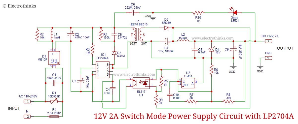
12V 2A Switch Mode Power Supply with LP2704A
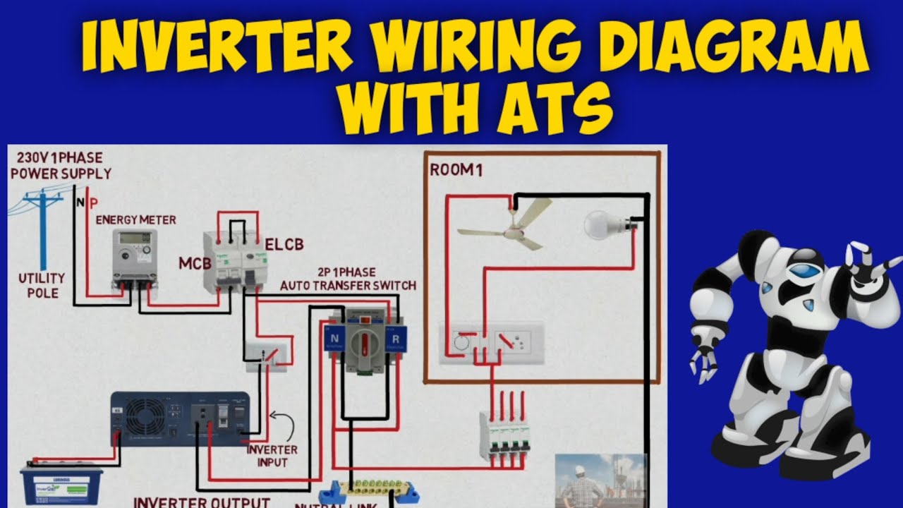
Automatic changeover switch | inverter wiring diagram with ATS | how to

Voltage Inverter Using Switch-Mode Regulator Circuit Diagram